Make sure that you have moved to blank new page (page1).
![]()
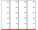
Add 4 BarGauges to the design panel.

Change the following properties to 1 with the order and resize components'
size by holding components' edge point.
property change order : MinorTickSpacing -> MajorTickSpacing -> MaxValue.
(This order is given because each property's values are relatively restricted.)

Now, the components look
![]() .
.
Assign m24~m27 to "Value Expression" field respectively.
Put 4 ImageDisplays in the design panel.
![]()
Assign m28~m31 to "Value Expression" field respectively.
Set image quantity as 2 and select image files to be displayed according to the
I/O status of monitoring bit.

While selecting image, an image mapping chooser dialog will pop up.

In this dialog, the "value" means that if value is 0, the selected
image will be shown when the monitoring bit I/O status is 0(off) for HD1100, and
monitoring byte value is 0 for HD1200.
Resize and relocate the ImageDisplay components to look
![]()
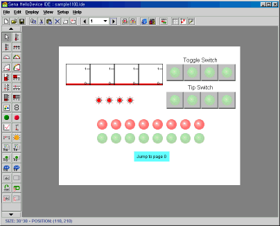
Place 4 LedToggleSwitches and 4 LedTipSwitches and assign its Value
Expression and Write Destination as from m24 to m31.

![]()
To catch the device-input-only bits (m0~m15)
Add Green and Red LED to the design panel.
![]()
Select two components and copy and paste them.
![]() and
and ![]()
Do the same totally 7 times and relocate.
![]()
Set Value Expression of these components from m0 to m15 respectively.
Set first 6 LED's audio alarm property "true" and assign them
different audio clips each.

When one of first 6 LED is on, it will play the assigned audio clip.
(Requires a sound card and speaker at client side

Finally, leave a way to return back to page 0 using PageJumpButton.
![]()
Set property as

Now this button looks
![]()
Page1 finished.

Go to the next section to see the output of through here works.